Atomic Force Microscope (AFM)

Basic Principles

Principle of AFM measurement

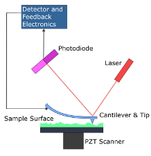
The AFM, which has been invented in 1986 by G. Binning, C. Quate and C. Gerber, uses the reflection of a laser beam from an oscillating cantilever to create a 3D image of the surface. This setup allows to investigate structures on the nanometer scale.
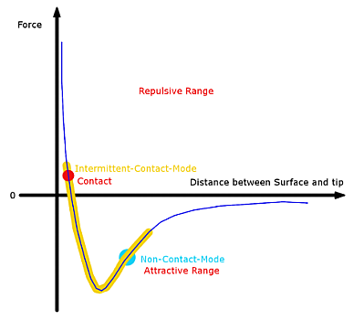
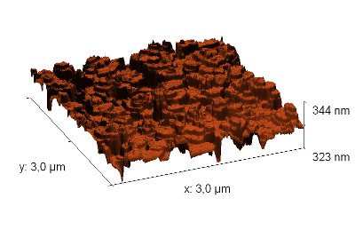
As the most crucial part the tip of the cantilever interacts with the surface, which causes the position of the laser spot to be changed. Depending on the distance between the sample surface and the tip, the cantilever behaves like a spring, with a spring constant of about 0.005N/m ~ 40N/m. There are several competing interactions, which can be distinguished depending on the range they dominate, i.e. relatively long range attractive interactions (van der Waals and other forces), and a repulsive short range interaction.

If the tip comes very close to the surface, the orbitals of the atoms will overlap and the cantilever feels a strong repulsive force. On the other hand, if the tip is retracted from the surface, at some point the long range interactions start to dominate and the tip is attracted.
There are several modes the cantilever can be used in: The most established ones are non-contact and intermittent-contact mode. In both cases the cantilever is probing the surface of the sample while performing oscillations like a spring mass system. Since the oscillations are influenced by interactions, so is the position of the laser spot. This is detected on a photo-sensitive diode. In general, non-contact mode is performed in the attractive force range and therefore considered to be safer. However, it is not necessarily easier to control as the tip can easily jump out of the suited range. This way the tip scans the surface.

Experimental Setup

AFM in noise protection cage
  • Most of the samples in our laboratory are prepared by organic molecular beam epitaxy.
  • To minimize possible disturbances caused by the environment, the sample as well as the AFM head are placed on a vibration compensation table.
  • Additionally, the AFM is placed inside a noise protection box.
  • To perform lateral movements in the micro-meter range a combination of accurate step motors and piezo crystals are used.
AFM-Head

Example

The picture to the left shows a typical AFM image of DIP (diindenoperylene), which was grown on a siliconoxide substrate under UHV conditions at about 130C. From the picture information about the topography and the roughness of the sample can be obtained. With the height information the AFM provides a 3D image of the surface, see the picture to the right.